Standard Disclaimer:
This is an account of what I did with my vehicle
and my own comments. Any use of this information is at the user's risk.
This exercise was performed on a 1G-GTE MK III Supra but advice to hand
is that 7M digital dashes as they're basically identical and that the 1JZ
dash is only different in omitting the oil pressure gauge.
The instrument cluster of the MK III is a little more than a collection
of instruments to inform the driver. As part of the vehicle electronics,
if it falls into disrepair, it can be the source of operational failures.
This is particularly so as the No. 1 speed sensor signal (used in shift
control of the automatic transmission) comes via dash instrument electronics.
The desire to rid the gremlins from my recently rebuilt transmission (along
with annoyance at the infamous unreliability of the fuel guage) prompted
me to embark on removing and inspecting my instrument cluster. Mine is
a right hand drive vehicle.
Removal of the instrument cluster itself is not difficult, although
requires a little patience (that's what cars are for). From memory, I removed
-
the centre console facia and heater controls
-
the small panel to the right of the steering wheel which houses the fog
light switch
-
steering column trim pieces (4 panels) and covered the column with a soft
cloth to protect the instrument cluster face on removal. The steering column
was dropped to its lowest adjustment and extended to be farthest from the
dash.
-
the "under trim" of the dash pad over the cluster. The screws were easily
accessible in their recesses. The under trim piece was fragile and required
careful removal. I will have to replace some of the screw recess bases
to properly secure it again.
The instrument cluster was thus revealed with six fixing screws securing
it to the dash. Having removed the screws, I could move the cluster assembly
outwards and get my hand behind to remove the 4 or 5 connectors from the
back (actually, to push painful little tags, wriggle and cajole the larger
connectors with expressions of frustration). With the harness disconnected,
the assembly could be carefully maneouvred out from its "cave" and past
the steering wheel toward the passenger side of the cabin. |
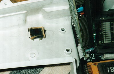
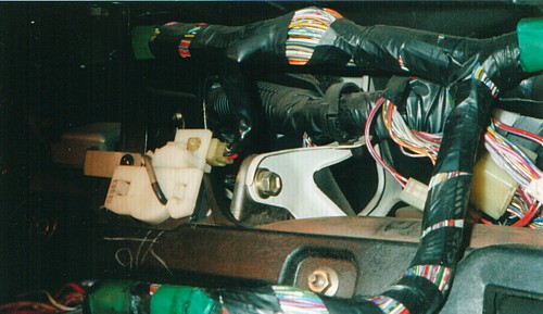 Here
you can see the neat white plastic speed sensor housing fed by the top
speedometer cable (not visible here) and secured to the front cabin brace
member behind the instrument assembly (removed in the photo, of course).
The sensor itself is a simple Hall effect chopper assembly.
Here
you can see the neat white plastic speed sensor housing fed by the top
speedometer cable (not visible here) and secured to the front cabin brace
member behind the instrument assembly (removed in the photo, of course).
The sensor itself is a simple Hall effect chopper assembly.
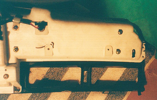 Once
the instrument assembly is removed from the vehicle, I placed it face down
on a SOFT SURFACE (I did not want the ugliest scratched instrument facia
when I put it back) where the vent registers could be carefully removed
from it. These were held by a couple of screws and plastic clips. If anyone
can preserve the plastic clips, he / she deserves a medal.
Once
the instrument assembly is removed from the vehicle, I placed it face down
on a SOFT SURFACE (I did not want the ugliest scratched instrument facia
when I put it back) where the vent registers could be carefully removed
from it. These were held by a couple of screws and plastic clips. If anyone
can preserve the plastic clips, he / she deserves a medal.
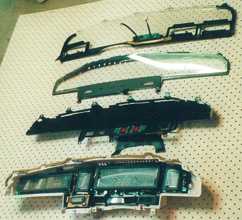 Once
the final screw is removed and the front panels carefully separated from
the back shell, the front was revealed to consist of three layers (all
smoke and mirrors to make it look flash - well hopefully not smoke.). Particularly
as the casing is not sealed, these layers accumulated a layer of grime.
Carefully cleaning each with a SOFT cloth and a plastic cleaner (I used
one called Plexus I use on my motorcycle and helmet) made a HUGE difference
to the dash appearance.
Once
the final screw is removed and the front panels carefully separated from
the back shell, the front was revealed to consist of three layers (all
smoke and mirrors to make it look flash - well hopefully not smoke.). Particularly
as the casing is not sealed, these layers accumulated a layer of grime.
Carefully cleaning each with a SOFT cloth and a plastic cleaner (I used
one called Plexus I use on my motorcycle and helmet) made a HUGE difference
to the dash appearance.
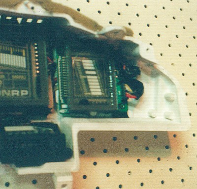 On
the right hand side is the engine temperature bar graph indicator unit.
It is a separate circuit board which may be removed. Note though that it
is on an angle to match the fuel guage on the other side of the speedometer
but its fixing screws do not fix its position i.e. when re-installing it
it needs to be adjusted to match the fuel guage angle and then the fixing
screw tightened to secure it. The fuel guage is fixed to the same circuit
board as the speedometer, so it could not be adjusted.
On
the right hand side is the engine temperature bar graph indicator unit.
It is a separate circuit board which may be removed. Note though that it
is on an angle to match the fuel guage on the other side of the speedometer
but its fixing screws do not fix its position i.e. when re-installing it
it needs to be adjusted to match the fuel guage angle and then the fixing
screw tightened to secure it. The fuel guage is fixed to the same circuit
board as the speedometer, so it could not be adjusted.
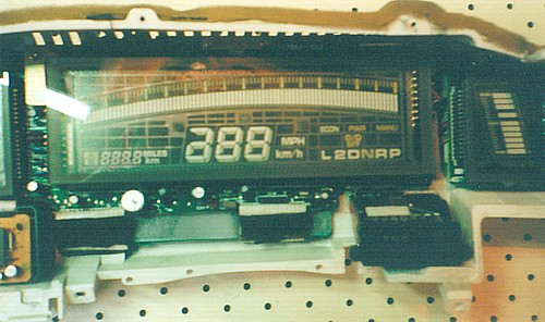 With
neither illumination nor masking, the speedometer unit showed all possible
displays. Sorry, anyone who wants to go over 399 kmh will need another
instrument (or convert to MPH but that just shifts it to a 399 MPH limit).
The odometer is a mechanical counter mechanism driven by an electric motor
on the lower right of the speedometer.
With
neither illumination nor masking, the speedometer unit showed all possible
displays. Sorry, anyone who wants to go over 399 kmh will need another
instrument (or convert to MPH but that just shifts it to a 399 MPH limit).
The odometer is a mechanical counter mechanism driven by an electric motor
on the lower right of the speedometer. 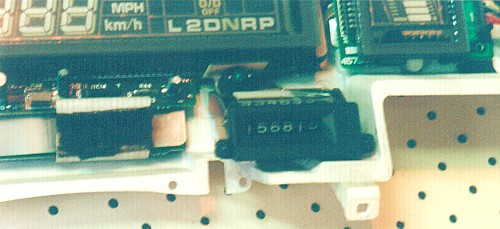 .
.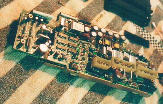 The
screws exposed at the rear of the cluster shell were removed to lift out
the speedometer subassembly for inspection as the major wiring harness
connectors attach directly to this module. As this subassembly comprises
three stacked daughter boards with interconnecting ribbon cables, I was
not eager to disassemble it. However, if suspected electrical connection
problems continue, I would separate these boards to examine the connector
solder joints on the back of the board shown on top.
The
screws exposed at the rear of the cluster shell were removed to lift out
the speedometer subassembly for inspection as the major wiring harness
connectors attach directly to this module. As this subassembly comprises
three stacked daughter boards with interconnecting ribbon cables, I was
not eager to disassemble it. However, if suspected electrical connection
problems continue, I would separate these boards to examine the connector
solder joints on the back of the board shown on top.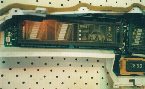 At
the left hand end of the cluster is the third instrument component which
comprises the boost and oil pressure guages as well as numerous vehicle
subsystem status indicators (TEMS, engine and doors). Note the earthing
pad on the far left of the component circuit board. This is the location
of the internal facia fixing screw. (Beats me how they assembled this part
... )
At
the left hand end of the cluster is the third instrument component which
comprises the boost and oil pressure guages as well as numerous vehicle
subsystem status indicators (TEMS, engine and doors). Note the earthing
pad on the far left of the component circuit board. This is the location
of the internal facia fixing screw. (Beats me how they assembled this part
... ) One
variation from the overall design is the seat belt warning light which
is separately mounted on the back shell and accommodated by a hole through
the boost etc instrument component. I guess this was only required in some
countries. All the same, I would have thought it cheaper to include it
in the component and simply not activate it ...
One
variation from the overall design is the seat belt warning light which
is separately mounted on the back shell and accommodated by a hole through
the boost etc instrument component. I guess this was only required in some
countries. All the same, I would have thought it cheaper to include it
in the component and simply not activate it ...