UP
WITH THE BOOST
Simple and Effective Boost Control for Toyota 1G-GTE Twin Turbo 6
Written by Jonathan Walker supragt@ihug.co.nz
[ Turbo control | Stage 1 | Stage 2 | Tuning ]
Stage 2: Connecting pneumatic equipment to turbocharger system
Step 1:
Although this tutorial doesn’t mention it, because there are none on my car, you will need to remove the heat shields from around the turbos, to make access to the ports easier.
Remove the compressor port to wastegate actuator hoses, 1 on each turbo, each will be held in place with 2 spring clips. These are difficult to access, a job for someone with small hands. Removing the rubber air intake pipe going from the AFM to the turbo air tee will make it easier. Remember to stuff rags in the exposed pipes to prevent entry of foreign particles!
The front turbo compressor outlet is below and to the rear of the distributor, and the hose goes underneath the compressor to the actuator. The rear turbo compressor outlet is much easier to get at, as is the actuator, both at the rear of the turbo, you can see clearly where the hoses go.
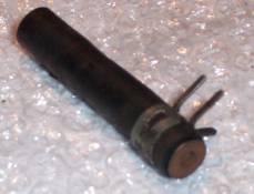
Take one of the original pipes for the actuators, remove the flow restrictor from the middle of the hose, and cut the hose in half. Push a slightly larger screw into the hose and clamp it with one of the original spring clips. Do this for each half. Use these plugged hoses to block off the compressor outlet ports. Secure with the two remaining spring clips.
|
|
<<< Use something like this to plug the now unused turbo compressor outlet ports, from which you have just removed the hoses. DO NOT FORGET TO DO THIS! This is what the compressor outlet ports look like (front turbo) >>> |
|
Step 2:
|
|
Clamp equal lengths of hose onto the wastegate actuator ports, and route to meet at the top next to the air intake pipe tee as shown. Try and avoid running the hose around the turbine/exhaust assembly. |
|
|
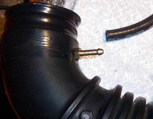
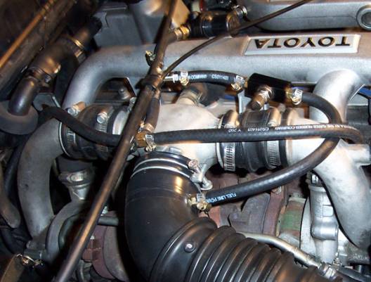
Drill an appropriately sized hole in the air pipe, and using the nut on the inside of the pipe, screw in, and secure the last hose tail to the air pipe, in the position shown. You may wish to you the other nut at this time, but I didn’t have room for it, the seal was fine without the top nut. This will connect to the needle valve. This was the most convenient position to place the hose tail for a short hose run. When completed, there should be no air leaking around the fitting. My intake pipe was cracked on the bottom, due to heat from the turbos and exhaust, that is why you see the black PVC tape, this is not part of the modification! |
|
|
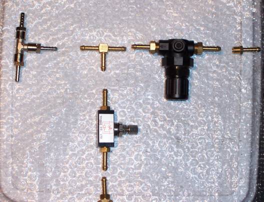
The layout of the pneumatic parts in the system. Starting on the right is the tee for the turbo wastegates. Connect this to the hoses coming off the actuators; ensure you don’t have more hose than you need. Interconnect these components exactly as they are shown above with appropriate lengths of hose. The large black valve is the pressure regulator valve; it must be connected with air flowing in the direction of the arrow. (Towards wastegates) The hose tail on the right is the one we tapped into the intake pipe. The needle valve is in the middle, and the bottom hose tail, is the one we just attached to the air pipe. |
|
|
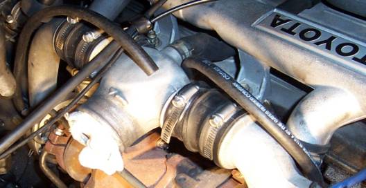
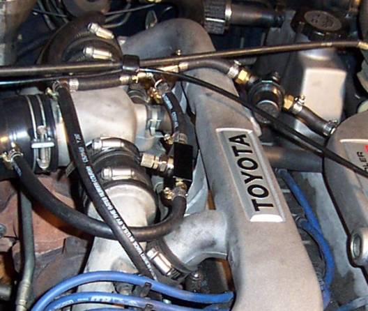
In this photo the throttle cable covers the tee join connecting the needle valve to the system (needle valve is below the TOYOTA) Attach all hoses and tighten all hose clamps. Ensure the pressure regulator is the right way around, and ensure all connections are correct: Intake pipe > Pressure Regulator > Tee Join 1 -> Needle valve > Air pipe 2 -> Tee join > Wastegate Actuators The finished product should look like this. I have not mounted the valves, as the hose prevents their movement to my satisfaction, and I don’t want long hose runs in the engine bay. Make sure the hoses are long enough for gentle radius bends so as not to pinch them off. |
|
|
In the end, we have a system that allows us greater control over the turbo boost. -As the engine speed increases, the boost pressure in the intake pipe increases, and this pressure is fed via the regulator valve to the wastegates, allowing exhaust to bypass the turbines controlling turbo speed at our set level. - On these CT12 turbochargers, 3.5-4PSI opens the wastegate, so the total pressure we wish to set on the regulator will be below 2 times this in order to open the wastegates to a lesser degree. (We treat the turbochargers as one, as the pressure feed is a total boost level.) - In the next section I will describe the process I used for tuning and setting the over boost level. |
[ Turbo control | Stage 1 | Stage 2 | Tuning ]